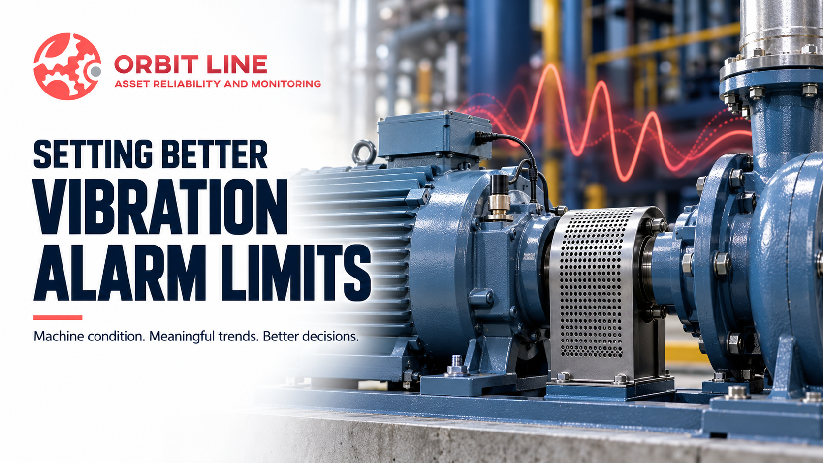
How to Set Vibration Alarm Limits for Industrial Machinery
By ORBIT LINE | Asset Reliability and Monitoring
A vibration alarm appears during a routine inspection. The overall reading has increased, but the machine is still running normally. Should maintenance take immediate action, increase monitoring or wait until the next planned shutdown?
The answer depends on more than the alarm value.
Motors, pumps, fans and gearboxes have different operating characteristics. Their vibration signatures depend on speed, load, construction, support conditions and mechanical condition. Applying the same alarm limit to every machine can result in unnecessary alerts—or missed opportunities to detect developing problems.
A useful vibration monitoring program combines three references: overall vibration severity, the machine’s historical behavior and diagnostic evidence.
Start with the Right Severity Reference
Overall vibration velocity is commonly used to assess the general vibration condition of industrial machinery. It provides a convenient summary of vibration measured within a defined frequency range.
Applicable parts of the ISO 20816 series provide guidance for evaluating vibration on specified machinery types. Before selecting limits, confirm that the standard applies to the equipment and measurement being evaluated.
Consider:
Machine type, rated power and operating speed.
Measurement location and direction.
Measurement units and frequency range.
Dynamic characteristics of the supporting structure.
Operating load and process conditions.
Relevant manufacturer recommendations.
Support conditions matter because the machine and its foundation respond together as a dynamic system. A support should not be classified as rigid or flexible simply from its appearance.
Severity guidance helps establish context. It does not identify the fault responsible for the vibration.
Compare the Machine with Its Own History
Historical data can reveal changes that a general severity limit may not highlight.
Consider an illustrative example: a pump normally operates at 0.8 mm/s RMS, but its latest reading reaches 2.2 mm/s RMS under similar operating conditions.
The reading may remain below an applicable overall alarm threshold, yet the increase deserves investigation. Possible explanations include a developing mechanical problem, a change in process conditions or an inconsistency in the measurement.
A baseline helps establish what is normal for that particular machine. As reliable history becomes available, baseline and statistical alarms can help identify meaningful departures from normal behavior.
Before accepting a baseline, confirm that the equipment is operating in a known, satisfactory condition. Otherwise, an existing problem may become part of the accepted reference.
Make Measurements Repeatable
A trend is only useful when its measurements are comparable.
Changes in sensor position, mounting method, speed, load or instrument settings can affect the reading. Without consistent collection practices, these differences may be mistaken for changes in machine condition.
For dependable trends:
Use clearly identified measurement points.
Maintain consistent sensor directions and mounting methods.
Use comparable instrument settings and frequency ranges.
Record actual operating speed and load.
Note relevant process conditions.
Record repairs, lubrication activities and other maintenance changes.
For variable-speed equipment, compare readings at similar speeds and loads, or establish separate reference conditions where appropriate.
Look Beyond the Overall Vibration Value
Two machines can have the same overall velocity reading and very different mechanical conditions.
One may have a stable spectrum dominated by normal running-speed vibration. The other may have developed new harmonics, sidebands or repeated impacts.
An overall reading compresses that information into a single value. It is useful for screening, but further analysis is needed to understand the symptoms.
Depending on the machine and suspected problem, an investigation may include:
Frequency spectrum analysis
Examines running-speed components, harmonics and other frequencies associated with the equipment.
Time waveform analysis
Helps reveal impacts, modulation and repeating events that may be less obvious in the overall value.
Phase measurements
Compare motion between measurement locations and support investigations of machine and structural behavior.
Acceleration and envelope analysis
Can help investigate bearing-related and impacting symptoms when suitable measurement settings are used.
Structural testing
May be needed when resonance or excessive structural response is suspected.
No single peak should be treated as proof of a particular fault. A diagnosis is stronger when several observations support the same explanation.
Confirm the Actual Operating Speed
Running speed is essential for interpreting vibration data.
The relationship is straightforward:
Running frequency in Hz = Actual RPM ÷ 60
For example, a shaft rotating at 1,800 RPM has a running frequency of 30 Hz. This is its 1× rotational frequency.
When speed changes, running-speed harmonics and other speed-related components change too. This is particularly important for equipment driven by variable-frequency drives.
Record the actual operating RPM whenever practical. Motor nameplate speed or a drive command alone may not represent the exact shaft speed during measurement.
Use Automated Diagnostics to Support the Review
Automated diagnostic tools can help organize measurements and highlight likely fault conditions. Their usefulness depends on accurate machine information, suitable measurements and the capabilities of the diagnostic system.
Review their findings alongside the spectrum, waveform, operating conditions and maintenance history.
When necessary, confirm the suspected problem through additional measurements or physical inspection. A diagnostic result should help guide the investigation and support an informed maintenance decision.
Turn Alarm Findings into Clear Actions
An effective condition report should explain more than whether a reading is acceptable or above an alarm limit.
It should identify:
What changed and where it was measured.
The operating conditions during measurement.
The evidence supporting the suspected cause.
The level of confidence in the assessment.
The recommended action and follow-up timing.
Depending on the findings and equipment criticality, the next step may be a repeat measurement, closer monitoring, a targeted inspection or planned corrective maintenance.
Alarm settings should also be reviewed after significant repairs, changes in operating conditions or improvements to the monitoring database. Any new baseline should reflect verified machine condition.
Better Alarms Support Better Maintenance Decisions
Vibration alarm limits are most useful when they reflect both the equipment and its operating history.
Use applicable severity guidance to assess the measured level, historical trends to recognize change, and diagnostic analysis to investigate the cause. Together, these references help maintenance teams prioritize work and plan corrective actions with greater confidence.
Condition Monitoring Support from ORBIT LINE
ORBIT LINE provides vibration analysis, machinery diagnostics and condition monitoring services to support industrial asset reliability.
Whether you are reviewing alarm settings, investigating abnormal vibration or improving measurement consistency, our team can help assess your equipment and develop practical maintenance recommendations.
Contact ORBIT LINE
Email: Admin@orbitlinetechnologies.com
Website: www.orbitlinetechnologies.com
Asset Reliability and Monitoring